1.3. Basics of Bonding
Covalent bonds are the result of constructively overlapping orbitals. Covalent bonds may be subdivided into two main types depending on how the orbitals involved overlap: sigma (σ) and pi (π) bonds.
1.3.1. Sigma (σ) Bonds
Sigma (σ) bonds result from direct (head-on) overlap between two orbitals. The simplest case to consider is the hydrogen molecule, H2. When we say that the two hydrogen nuclei share their electrons to form a covalent bond, what we mean is that the two spherical 1s orbitals overlap and contain two electrons with opposite spin (Figure 1.9).
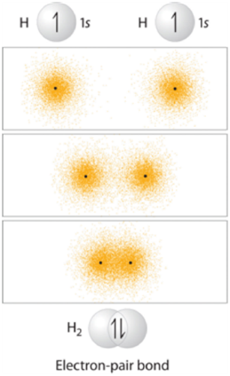
Figure 1.9 – Representation of the Sigma (σ) Bond Formed by H2.
These two electrons are now attracted to the positive charge of both of the hydrogen nuclei, with the result that they serve as a sort of ‘chemical glue’ holding the two nuclei together.
The combination of an s orbital with another s orbital described above is the simplest to visualize (Figure 1.10). The two orbitals directly overlap with each other, forming an area between the two nuclei where the electrons are shared.
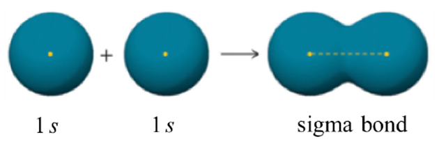
Figure 1.10 – Representation of the Sigma (σ) Bond Formed by the Combination of an s Orbital with an s Orbital.
However, a σ bond may arise from any direct overlap between two properly aligned orbitals of the same phase. The combination of an s orbital with an aligned p orbital (Figure 1.11a) is slightly more complicated but follows the same pattern.
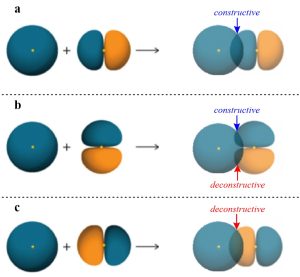
Figure 1.11 – Representations of the Sigma Bond (σ), Non-Bonding Interaction, and Sigma Anti-Bond (σ*) Formed by Differently Aligned Combinations of an s Orbital with a p Orbital.
The idea of constructive overlap is important here. That is, the phase of the two orbitals being combined must be the same to form a covalent bond. In this case phase is being represented by colour, with the ‘blue’ s orbital constructively overlapping with the ‘blue’ portion of the p orbital.
Imagine the p orbital above were rotated 90° clockwise on the page (equivalent to using a pz instead of a px orbital; Figure 1.11b). Now, as the two orbitals come together any constructive overlap between ‘blue’ portions at the top would be cancelled out by a deconstructive overlap between the ‘blue’ portion of the s orbital and the ‘orange’ portion at the bottom of the p orbital. This means a covalent bond would not be possible with this alignment of orbitals, with every constructive overlap matched by an equal deconstructive one.
Imagine the p orbital above were instead rotated 180° clockwise on the page (equivalent to switching the ‘blue’ and ‘orange’ portions; Figure 1.11c). Now, as the two orbitals come together there is instead a deconstructive overlap between the ‘blue’ portion of the s orbital and the ‘orange’ portion of the p orbital. Instead of a stabilizing bond being formed, a destabilizing anti-bonding orbital is generated (σ*). The involvement of anti-bonding orbitals in chemical bonds is complex and well beyond the scope of this text; at an introductory level assume anti-bonding orbitals are not important for a discussion of bonding, but play a crucial role in many kinds of chemical reactions.
To avoid confusion later it is important to clarify that σ bonds do not require an s orbital in their formation. For example, two properly aligned p orbitals may overlap to form a σ bond (Figure 1.12). In other words, the only important requirement is that the two portions overlapping combine constructively and in a direct overlap. This specific combination (two p orbitals forming a sigma bond) is uncommon in organic chemistry but plays important roles in inorganic chemistry.
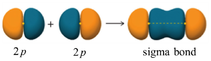
Figure 1.12 – Representation of the Sigma (σ) Bond Formed by the Combination of a p Orbital with a p Orbital.
1.3.2. Pi (π) Bonds
Pi (π) bonds result from indirect (side-on) overlap between two orbitals. Unlike σ bonds, the two orbitals are not able to directly overlap, instead simply coming closer together and slightly ‘bending’ to constructively overlap.
In simple organic systems all π bonds result from the indirect overlap of two p orbitals (Figure 1.13). As a result there are two areas, one above and one below the nuclei, which form the bond. The two lobes together make one π bond.
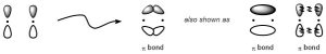
Figure 1.13 – Representation of the Pi (π) Bond Formed by the Combination of a p Orbital with a p Orbital.
The simplest case to consider is ethylene, which contains a carbon double bonded to another carbon (Figure 1.14). The first bond between them is a σ bond, with one of the lines between them representing this bond. The second bond between them is a π bond formed by the combination of a p orbital from each of the carbons. The other line represents this bond. Notice that even though there are three areas of electron density (lobes), there are only two bonds because the π bond is made from overlap of both lobes on the p orbitals.
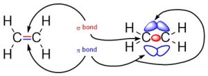
Figure 1.14 –Representation of π and σ Bonds Between Carbons in Ethylene.
In more complex systems, including those involving heavy metal elements, more complex orbitals (commonly d orbitals) may also be involved. These do not play a role in any systems encountered in this text.
1.3.3. Polarized Bonds and Electronegativity
In covalent bonds electrons are shared between the two atoms involved. When the two atoms involved are the same element (and barring other factors) the electrons are shared equally. However, not all elements have the same affinity for electron density around them. We can quantify a measurement called electronegativity, which is defined as the relative ability of an atom to attract electrons to itself in a chemical compound. Electronegativity of an atom is not a simple, fixed property that can be directly measured in a single experiment. In fact, an atom’s electronegativity should depend to some extent on its chemical environment because the properties of an atom are influenced by the neighboring atoms in a chemical compound. Nevertheless, when different methods for measuring the electronegativity of an atom are compared, they all tend to assign similar relative values to a given element. The most common values used are those in the Pauling scale (Figure 1.15).
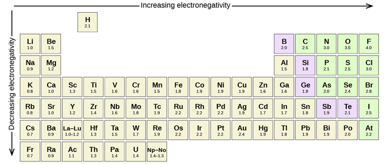
Figure 1.15 – Pauling scale electronegativities of elements.
When two atoms with different electronegativities are covalently bonded together an unequal sharing of electrons occurs. This is referred to as a polar covalent bond. The atom that takes extra electron density (the more electronegative atom) is denoted with a symbol, δ–, while the atom that gains less electron density is denoted with the symbol δ+. These symbols emphasize that there are partial negative and positive charges on those atoms. Polar covalent bonds can be thought of as being similar to ionic bonds, but where the electrons are still ‘shared’ between the two atoms (Figure 1.16).
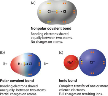
Figure 1.16 – The Electron Distribution in a Nonpolar Covalent Bond, a Polar Covalent Bond, and an Ionic Bond.
In general, an electronegativity difference of >0.4 is required for us to consider a bond polar. For instance, a carbon-hydrogen bond is not polar (0.4 difference), but a carbon-nitrogen bond is (0.5 difference) and a carbon-fluorine bond (1.5 difference) is even more so (Figure 1.17).
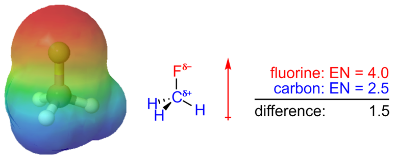
Figure 1.17 – Electrostatic Potential Map and Dipole Moment of Fluoromethane.
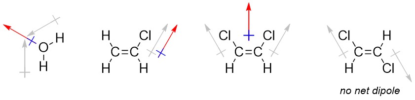
It is occasionally useful to denote the direction that a bond or molecule is polar in. Convention uses a crossed arrow pointing in the direction of the more negative portion. Be aware that in other areas of chemistry, particularly inorganic chemistry, this symbol may be used to mean other things. The arrow convention is more useful when describing the overall direction of polarity in a molecule (a sum of vectors; a net dipole), such as when there are multiple polar bonds oriented in different directions.
1.3.3.1 How to Determine the Overall Direction of Polarity (Net Dipole)
Determining the net dipole (sometimes called dipole moment) from a molecular structure can be complicated when there is more than one type of polar bond (e.g. a C-Cl bond and a C-O bond) because they do not affect the net polarity to the same degree. At an introductory level these differences are typically ignored and complex examples are avoided. Each polar bond is considered an equivalent ‘pull’ in the direction of the more electronegative atom and the overall direction being pulled towards is determined. When present three-dimensional structure (see Section 1.4) must be considered to accurately determine the overall direction of the net dipole. With practice this process can be streamlined and done internally.
- Determine which bonds are polar.
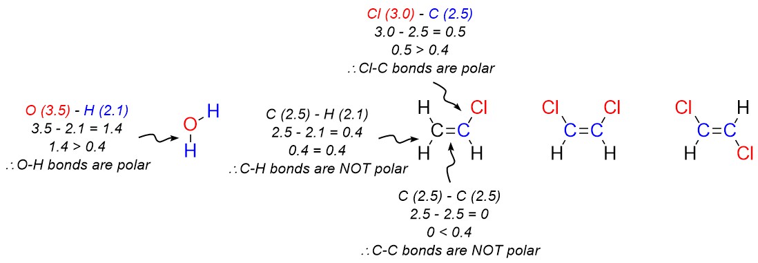
- Add crossed arrows to each polar bond pointing from the less electronegative atom to the more electronegative atom.
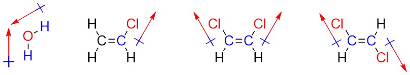
- Sum the vectors. This can be done intuitively by considering each arrow as a ‘pull’ in the direction it points to; if the molecule were being pulled in the indicated directions, what direction would it actually move in?