
Chapter 7 Review
Key Terms
Cramer’s rule
An explicit formula for the solution of a system of linear equations with as many equations as unknowns, valid whenever the system has a unique solution.
linear circuit
An electronic circuit in which, for a sinusoidal input voltage of frequency  any steady-state output of the circuit (the current through any component, or the voltage between any two points) is also sinusoidal with frequency
load resistor
An electrical component or portion of a circuit that consumes electric power. Normally, the term “load” is used to refer specifically to the active component for which power consumption is mainly intended, as opposed to internal resistance or resistors used in conjunction with capacitors or inductors for timing.
maximum power transfer theorem
Maximum power is transferred to a load when the internal resistance equals the load resistance; for a Thévenin-equivalent circuit, this is true when the load resistance equals the Thévenin resistance.
mesh analysis
A method that is used to solve planar circuits for the currents (and indirectly the voltages) at any place in an electrical circuit.
mesh current
The currents defined in mesh analysis as flowing around each loop of a planar circuit. The actual current through each branch of the circuit is found as a combination of the mesh currents in that branch.
planar circuit (mesh)
An electrical circuit that can be drawn on a plane surface with no wires crossing each other.
superposition theorem
The response (voltage or current) in any branch of a linear circuit having more than one independent source equals the algebraic sum of the responses caused by each independent source acting alone, where all the other independent sources are replaced by short circuits.
Thévenin-equivalent circuit
A simple circuit, equivalent to any more complex linear circuit, involving the Thévenin voltage and Thévenin resistance relative to a particular load. In the Thévenin-equivalent circuit, the Thévenin voltage and resistance are connected in series with the load.
Thévenin resistance
One component of a linear circuit’s Thévenin-equivalent, found by removing the load resistor from the original circuit and calculating the total equivalent resistance between the two load connection points.
Thévenin’s theorem
An electrical circuit theorem through which any complex linear circuit may be replaced by its Thévenin-equivalent with respect to a given load.
Thévenin voltage
One component of a linear circuit’s Thévenin-equivalent, found by removing the load resistor from the original circuit and calculating the potential difference from one load connection point to the other.
Key Equations
| Cramer’s rule |  |
| Current through a load resistor |  |
| Voltage across a load resistor |  |
| Power dissipated in a load resistor |  |
Summary
7.1 Mesh Analysis
- Steps in mesh analysis method:
- Draw mesh current loops, ensuring:
- each loop is unique; and
- all circuit elements—voltage sources, resistors, capacitors, inductors, etc. and short circuits—are covered by at least one loop.
- Apply loop rule as described in Kirchhoff’s Rules (particularly with reference to Figure 6.3.5) and solve simultaneous equations.
- Add or subtract mesh currents in branches that are covered by multiple loops, depending on the direction of each loop and the sign of each current calculated in step 2.
- Draw mesh current loops, ensuring:
- When
 and
and  are known, the elements of
  are given by Cramer’s rule:
![\[I_i=\frac{\mathrm{det}(\mathbf{R}_i)}{\mathrm{det}(\mathbf{R})},\]](https://openpress.usask.ca/app/uploads/quicklatex/quicklatex.com-975d9b3bc4f48d9c18e48370bc0077d1_l3.png "Rendered by QuickLaTeX.com")
where
 is the
  -th element of and
  is the matrix formed by replacing the -th column of with .
 - Steps to read off and directly from a planar circuit:
- Draw one mesh current loop inside each loop of the circuit.
- Work your way around each loop , reading off terms
 and
and  as:
as:
- is the sum
 for each voltage source
 that passes from negative to positive, and
  for each voltage source
 that passes through from positive to negative,
  is the sum
  for each resistor
 that passes, and
- is the sum
 for each resistor
 passed by a mesh current
  adjacent to .
7.2 Superposition Theorem
- Linear circuits can be analysed by calculating contributions to current for each voltage source independently
- Steps in superposition method:
- Replace all potential sources but one with a short circuit; find the voltage/current through each branch of the network.
- Repeat for each potential source.
- Add up all the separate voltages/currents in each branch.
7.3 Thévenin’s Theorem
- Any linear circuit containing several voltage sources and resistors can be simplified to an equivalent circuit with a single voltage source and resistance connected in series with a load. Specifically, the three components connected in series are:
- Load resistor,
 ;
; - Thévenin voltage
 , found by removing from the original circuit and calculating the potential difference from one load connection point to the other;
 - Thévenin resistance
 , found by removing from the original circuit and calculating the total equivalent resistance between the two load connection points.
- Load resistor,
- Once the Thévenin voltage and resistance are determined, the Thévenin-equivalent circuit is redrawn with the Thévenin voltage attached to the Thévenin resistance in series, and any load resistance attached between the two connection points
- Maximum power transfer theorem: maximum power is transferred to a load when the internal resistance equals the load resistance; for a Thévenin-equivalent circuit, this is true when the load resistance equals the Thévenin resistance
Answers to Check Your Understanding
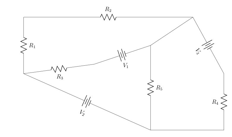
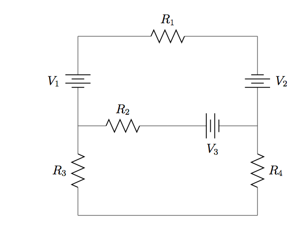
7.1 a.
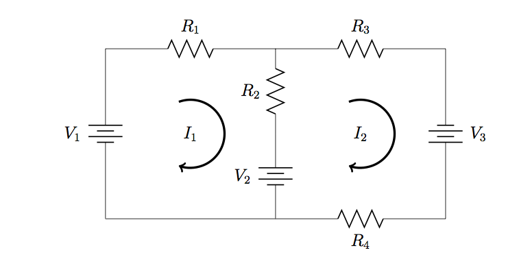
![\[\mathbf{V}=\left(\begin{array}{c}-V_1\\V_1-V_2\\V_3\end{array}\right),~~~\mathbf{R}=\left(\begin{array}{ccc}-(R_1+R_2+R_3)&R_3&0\\R_3&-(R_3+R_5)&R_5\\0&R_5&-(R_4+R_5)\end{array}\right)\]](https://openpress.usask.ca/app/uploads/quicklatex/quicklatex.com-b2c3e95b754ebc118ff20cca8367968c_l3.png "Rendered by QuickLaTeX.com")
b.
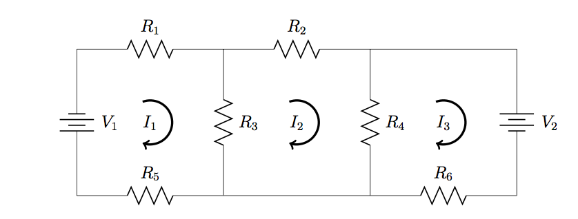
![\[\mathbf{V}=\left(\begin{array}{c}V_1-V_2\\V_2\\-V_3\end{array}\right),~~~\mathbf{R}=\left(\begin{array}{ccc}-(R_1+R_4)&0&R_4\\0&-(R_2+R_3)&0\\R_4&0&-(R_4+R_5+R_6)\end{array}\right)\]](https://openpress.usask.ca/app/uploads/quicklatex/quicklatex.com-5f81547c0407f6b0e4f1e0b42b1047a6_l3.png "Rendered by QuickLaTeX.com")
c.
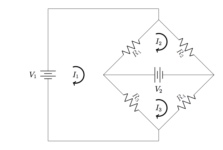
![\[\mathbf{V}=\left(\begin{array}{c}-V\\0\\0\end{array}\right),~~~\mathbf{R}=\left(\begin{array}{ccc}-(R_1+R_4)&R_1&R_4\\R_1&-(R_1+R_2+R_3)&R_3\\R_4&R_3&-(R_3+R_4+R_5)\end{array}\right)\]](https://openpress.usask.ca/app/uploads/quicklatex/quicklatex.com-3fc3e7826e500329fbc44adf18373006_l3.png "Rendered by QuickLaTeX.com")
7.2 Replacing the  source with a short means current from the
  source passes through the short. With the source replaced with a short, the current through the
  resistor due to the source is
![\[I_{7\Omega}=\frac{6.00~\mathrm{V}}{7.00~\Omega}=\frac{6.00}{7.00}~\mathrm{A}.\]](https://openpress.usask.ca/app/uploads/quicklatex/quicklatex.com-17960c34e2c17ea5f72b575fe7c3db1a_l3.png "Rendered by QuickLaTeX.com")
Therefore, the current through the resistor is  and the power dissipated is
  In fact, since the
  -resistor is connected directly to the terminals of the source, the current is
  regardless of the value of the battery.
7.3.  ,
,  .
.
Conceptual Questions
7.1 Mesh Analysis
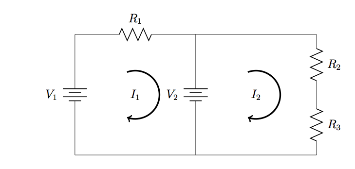
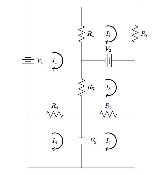
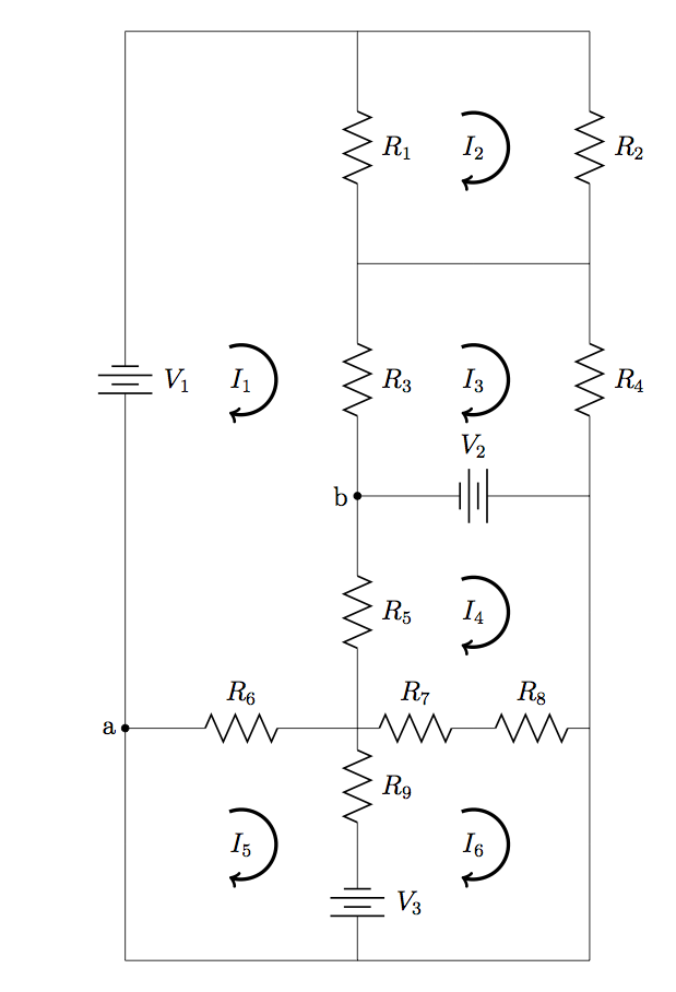
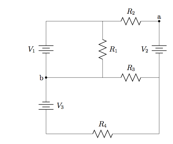
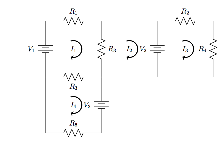
1. Sally and Frank are asked to find the and matrices for the circuit below. They both follow the procedure for reading off matrix elements described in Mesh Analysis. When comparing results, they find that they have the same elements in the first rows of both and , but the elements in the second and third rows of their matrices are swapped. How did this happen? Did one of them make an error? If given values for the voltages and resistances, should they expect to find the same currents through each component? Explain.
7.2 Superposition Theorem
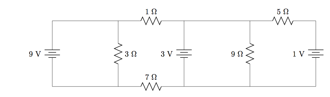
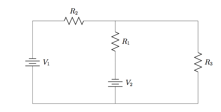
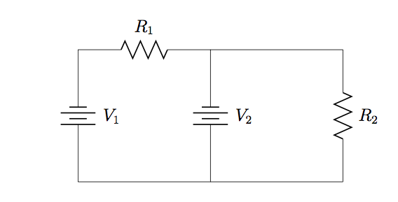
2. How much power is used by the  -resistor in the circuit below? How much power is used by the
  -resistor? Explain why the answers are obvious, with no need to do any work. (Hint: this problem is best approached using superposition method).
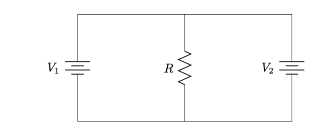
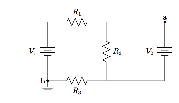
3. (a) Use superposition theorem to determine the potential difference across the resistor in the circuit below. (b) Explain why mesh analysis is a bad approach to use for this problem (e.g. you could demonstrate this by applying the mesh strategy and Cramer’s rule to calculate mesh currents and interpret the result).
7.3 Thévenin’s Theorem
4. Efficiency. The efficiency of a circuit is defined as the ratio between the power used by a load and the total power used. (a) Show that the general expression for efficiency can be written as
![\[\eta=\frac{R_L}{R_{\mathrm{th}}+R_L}.\]](https://openpress.usask.ca/app/uploads/quicklatex/quicklatex.com-2b247dfef1df4ee40e3db48b76fea981_l3.png "Rendered by QuickLaTeX.com")
For any given and , show that: (b) the condition for minimum efficiency ( ) corresponds to maximum current, but the voltage across and power dissipated at the load are both small; (c) the condition for maximum efficiency (
 ) corresponds to maximum voltage across the load, but current through and power dissipated at the load are both small; (d) the condition of maximum power transfer (
 ), while only moderately efficient, corresponds to both moderate voltage across and moderate current through the load. (Hint: You may find it useful to refer to Equations 7.3.1-7.3.3).
Problems
7.1 Mesh Analysis
5. Apply Cramer’s rule to find expressions for  and
and  in terms of the given resistances and voltages.
6. Refer to the circuit in Problem 5, with  ,
,  ,
,  ,
,  , and
, and  . Apply Cramer’s rule to calculate the values of and .
7. Apply Cramer’s rule to find expressions for and in terms of the given resistances and voltages.
8. Refer to the circuit in Problem 7, with , ,  ,
,  ,
,  ,
,  , and
, and  . Apply Cramer’s rule to calculate the values of and .
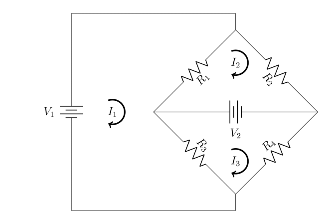
9. Apply Cramer’s rule to find expressions for , , and  in terms of the given resistances and voltages.
10. Refer to the circuit in Problem 9, with , , , , ,  ,
,  , and
, and  . Apply Cramer’s rule to calculate the values of , , and .
11. Apply Cramer’s rule to find expressions for , , and in terms of the given resistances and voltages.
12. Refer to the circuit in Problem 11, with , , , , , and . Apply Cramer’s rule to calculate the values of , , and .
13. Find expressions for the total power supplied by all voltage sources and the total power dissipated at all resistors, and confirm that these are equal.
14. Refer to the circuit in Problem 13, with , , , , and . Calculate the total power supplied by all voltage sources and the total power dissipated at all resistors, and confirm that the two values are equal.
15. Find expressions for the total power supplied by all voltage sources and the total power dissipated at all resistors, and confirm that these are equal.
16. Refer to the circuit in Problem 15, with , ,  , , , , and . Calculate the total power supplied by all voltage sources and the total power dissipated at all resistors, and confirm that the two values are equal.
17. Find expressions for the total power supplied by all voltage sources and the total power dissipated at all resistors, and confirm that these are equal.
18. Refer to the circuit in Problem 17, with , , , , , , and . Calculate the total power supplied by all voltage sources and the total power dissipated at all resistors, and confirm that the two values are equal.
19. Find expressions for the total power supplied by all voltage sources and the total power dissipated at all resistors, and confirm that these are equal.
20. Refer to the circuit in Problem 19, with , , , , , , and . Calculate the total power supplied by all voltage sources and the total power dissipated at all resistors, and confirm that the two values are equal.
21. Find expressions for the current through and power dissipated at  in terms of the given resistances and voltages.
22. Refer to the circuit in Problem 21. Calculate (a) the mesh current values and (b) the power supplied by each voltage source, when , , , , , , , and  .
.
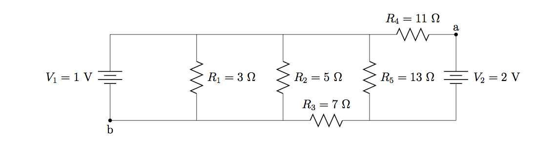
23. Find the potential difference  between points
  and
and  in the following circuit diagram.
24. (a) Use a computer to calculate the mesh currents  in the following circuit diagram, when , , , , , , , ,
  ,
,  ,
,  , and
, and  . (b) Calculate the potential difference across and
  , confirming that
  .
.
7.2 Superposition Theorem
25. Use superposition method to find an expression for the current through and power dissipated by  in the circuit below.
26. Use superposition method to calculate the current through and power dissipated by in the circuit from problem 25, when , , , and .
27. Use superposition method to find expressions for (a) the currents through each resistor in the circuit below, and (b) the potential difference between points and .
28. Refer to the circuit in problem 27, with , , , , and . Use superposition method to calculate (a) the current through each resistor, and (b) the potential difference between points and .
29. Use superposition method to find an expression for the current through and power dissipated by  in the circuit below.
30. Use superposition method to determine the current through and power dissipated by in the circuit from problem 29, when , , , , , , and .
31. Use superposition method to find expressions for (a) the current through each resistor in the circuit from Problem 29, and (b) the potential difference between points and .
32. Refer to the circuit in problem 29, with, , , , , , and . Use superposition method to calculate (a) the current through each resistor, and (b) the potential difference between points and .
7.3 Thévenin’s Theorem
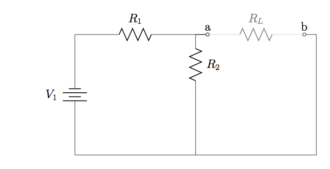
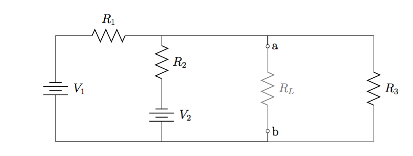
33. Find expressions for and with respect to in the circuit diagram below.
34. Refer to the circuit diagram in Problem 33, with ,  , and
, and  . Calculate (a) and with respect to , and (b) the maximum amount of power that can be used by .
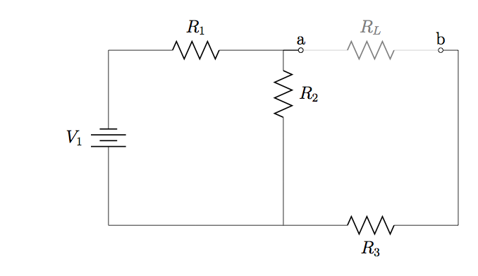
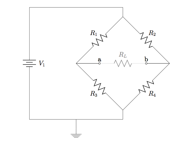
35. Find expressions for and with respect to in the circuit diagram below.
36. Refer to the circuit diagram in Problem 35, with , , , and  . Calculate (a) and with respect to , and (b) the maximum amount of power that can be used by .
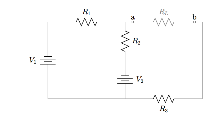
37. Find expressions for and with respect to in the circuit diagram below.
38. Refer to the circuit diagram in Problem 37, with , , , , and . Calculate (a) and with respect to , and (b) the maximum amount of power that can be used by .
39. Find expressions for and with respect to in the circuit diagram below.
40. Refer to the circuit diagram in Problem 39, with , , , , and . Calculate (a) and with respect to , and (b) the maximum amount of power that can be used by .
41. Find expressions for and with respect to in the circuit diagram below.
42. Refer to the circuit diagram in Problem 41, with , , , and , and  . Calculate (a) and with respect to , and (b) the maximum amount of power that can be used by .
Additional Problems
43. Find the current through, and the power dissipated by  in the circuit below using (a) mesh analysis method and (b) superposition method.
44. Find the current through  and
and  in the circuit below using (a) mesh analysis method and (b) superposition method.
Candela Citations
- Authored by: Daryl Janzen. Provided by: Department of Physics & Engineering Physics, University of Saskatchewan. License: CC BY: Attribution
