
7.2 Superposition Theorem
LEARNING OBJECTIVES
- Solve linear circuits by the superposition method
The linearity of resistive networks that satisfy Ohm’s law allows a number of simplifying approaches to be taken in their analysis. Mesh Analysis makes use of linearity in its assumption that the current through any branch can be broken down into “parts”, the summation of which is the actual current through the branch. Similarly, superposition theorem tells us that the voltage across any branch of a circuit can be broken up as a linear combination of potential differences due to each voltage source in a resistive network, considered individually. Circuit analysis by superposition therefore follows a process of replacing all voltage sources but one within a network with short circuits, then using the summation rules of series-parallel combinations of resistors described in Resistors in Series and Parallel and determining the voltage across and current in each branch due to the remaining voltage source, and then repeating this process for all voltage sources and superposing the results.
Problem-Solving Strategy: Superposition
- Replace all potential sources but one with a short circuit; find the voltage/current through each branch of the network.
- Repeat for each potential source.
- Add up all the separate voltages/currents in each branch.
In practice, superposition theorem is often not an effective approach to circuit analysis due to the fact that the circuit needs to be analysed as many times as there are voltage sources. However, some circuits are in fact very quickly analysed using superposition, and, even when they may not be, there are times when we need to work out a solution by hand, and the superposition approach is more efficient than using Cramer’s rule or inverting matrices by hand (e.g. for higher than three loop-circuits with only a couple of voltage sources). At these times it is helpful to have the superposition theorem to fall back on to make life a little easier. The following example demonstrates how this works.
EXAMPLE 7.2.1
Calculating Current Using Superposition Theorem
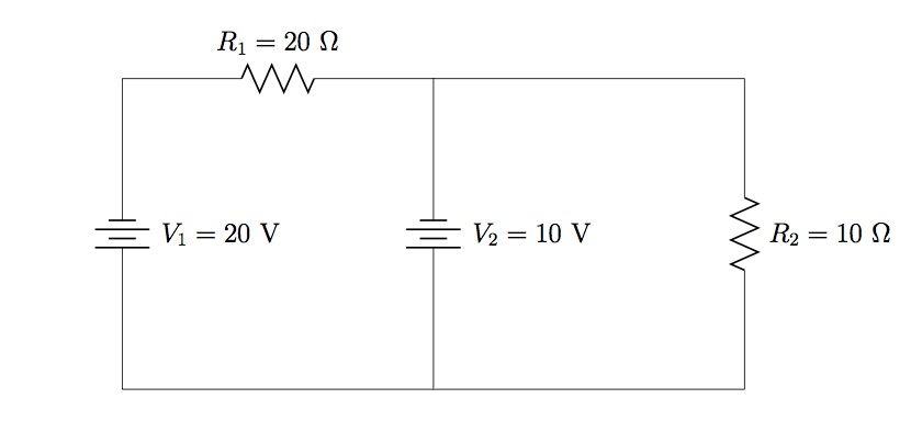
Find the power supplied by the voltage sources and the power dissipated by the resistors in Figure 7.2.1, using the superposition approach.
(Figure 7.2.1) 
Strategy
Remove each voltage source in turn and determine the voltage across and current through the three remaining components. Add the results of both calculations and use currents through each component to determine the power supplied/dissipated by each.
Solution
First, removing  , the short means that the potential must be the same on either side of
  —i.e. there is no potential difference across due to
  , and current preferentially flows (counter-clockwise) through the short. The potential difference across
  is simply
  Thus,
Thus,
![\[I_{R_1}(V_1)=\frac{V_1}{R_1}=1~\mathrm{A}~\mathrm{to~left},~~~~~I_{R_2}(V_1)=\frac{0}{R_2}=0.\]](https://openpress.usask.ca/app/uploads/quicklatex/quicklatex.com-753948c9c2e0823a8a127af69bbec9bb_l3.png "Rendered by QuickLaTeX.com")
With replaced by a short, is now connected across both resistors in parallel. Due to the orientation of , current flows through to the right and flows up through , with values,
![\[I_{R_1}(V_2)=\frac{V_2}{R_1}=0.5~\mathrm{A}~\mathrm{to~right},~~~~~I_{R_2}(V_2)=\frac{V_2}{R_2}=1~\mathrm{A}~\mathrm{upward}.\]](https://openpress.usask.ca/app/uploads/quicklatex/quicklatex.com-00789bd08e45f8862100e4df61d0d8c1_l3.png "Rendered by QuickLaTeX.com")
Therefore, the total currents through the two resistors are
![\[I_{R_1}=0.5~\mathrm{A}~\mathrm{to~left},~~~~~I_{R_2}=1~\mathrm{A}~\mathrm{upward}.\]](https://openpress.usask.ca/app/uploads/quicklatex/quicklatex.com-748b4f5b9078f098f25311c3f36c3aaa_l3.png "Rendered by QuickLaTeX.com")
Furthermore, note that  and points downwards, since is in series with ; and, by the junction rule,
The power supplied by the voltage sources is
![\[P_{\mathrm{supplied}}=\sum_iI_{V_i}V_i=(0.5~\mathrm{A})(20~\mathrm{V})+(0.5~\mathrm{A})(10~\mathrm{V})=10~\mathrm{W}+5~\mathrm{W}=15~\mathrm{W}.\]](https://openpress.usask.ca/app/uploads/quicklatex/quicklatex.com-cb13b45af435d4531cc650c8ca6a5f5a_l3.png "Rendered by QuickLaTeX.com")
And the power dissipated by the resistors is
![\[P_{\mathrm{dissipated}}=\sum_iI_{R_i}^2R_i=(0.5~\mathrm{A})^2(20~\Omega)+(1~\mathrm{A})^2(10~\Omega)=5~\mathrm{W}+10~\mathrm{W}=15~\mathrm{W}.\]](https://openpress.usask.ca/app/uploads/quicklatex/quicklatex.com-645064dafa8925cf1196d374b15a12a6_l3.png "Rendered by QuickLaTeX.com")
Significance
The power supplied by the two voltage sources equals the power dissipated by the two resistors, as required.
CHECK YOUR UNDERSTANDING 7.2
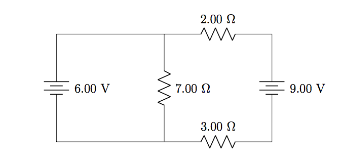
Use superposition to determine the current through and power dissipated by the  -resistor in the circuit below. Would these values change if the
  source were replaced by a short? What if its voltage were doubled to
  ? Explain.
It is important to note that the superposition theorem can only be used when the basic relationships between variables are linear. For instance, current and voltage are linearly related, so it is possible to work out contributions to the voltage across each resistor in a network individually, calculate currents individually, and then add up the results. This can be done because current is proportional to voltage for a given resistor by Ohm’s law.
The requirement of linearity in the underlying relations means that the superposition is actually only applicable for determining the voltages across and currents through circuit components. Power, on the other hand, does not enjoy these nice linear relationships. Therefore, it is not possible to find the power supplied by each potential source separately and add the results; nor is it possible to find the power dissipated by each resistor in the presence of individual voltage sources and sum the results to find total power dissipated by resistors.
Candela Citations
- Authored by: Daryl Janzen. Provided by: Department of Physics & Engineering Physics, University of Saskatchewan. License: CC BY: Attribution
